
Direct-drive servo tutorial, application update
Solving low speed rotary servo applications with direct-drive motors avoids hidden initial costs, while saving money over the life of the machine. Example shows $73,000 annual savings on a widget-making machine.
Learning Objectives
- Understand the basics of direct-drive motor designs.
- Learn what type of applications are suited to direct-drive motors.
- Calculate the applications savings with shorter cycle times.
Understanding industrial direct-drive servo motor technology helps apply servomotors in a variety of applications. What is a direct-drive motor? When can using a direct-drive servomotor deliver better performance metrics than transmission-based alternatives?
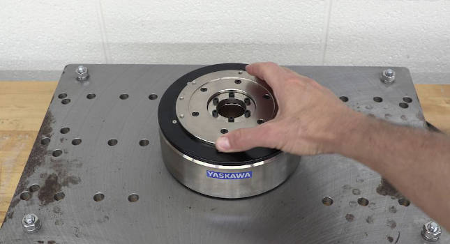
Figure 1 shows a typical direct-drive motor mounted on a steel plate, with a hand turning the rotating flange. A direct drive motor is characterized by the cylindrical “donut” shape with a hole through the middle of the rotating flange. There’s typically no motor shaft as with a standard servomotor. The rotating part of a direct-drive motor still is called the rotor, with mounting holes along the flange. The load attaches directly to the flange of the motor. That’s the source of the name: “direct-drive motor.”
The part that does not move is called the stator. It’s where the cables connect. The stator also has mounting holes, which bolt to the machine frame.
Motor vocabulary: Direct-drive motors also may be called a torque motor or a hub motor.
Direct-drive motors have much higher torque than a standard servomotor, and much lower speed. They trade speed for torque, with typical top speeds of just a few hundred RPMS down to only tens of RPMs with extremely high torque.

Figure 1 shows a typical direct-drive motor mounted on a steel plate, with a hand turning the rotating flange. Courtesy: Yaskawa America Inc.
Direct-drive motor sizing, selection
The speed torque curve of a direct drive motor is a lot like a servomotor with a gear reduction around 10:1 and up, sometimes as high as 100:1. Figure 2 shows the speed torque curve along with the RMS and peak operation points for an application that would fit either a geared servomotor or a direct-drive motor. Both of the systems in this example can supply torque up to about 28 Nm, and peak torque up to about 50 Nm with top speed just over 100 RPM.

Figure 2 shows the speed torque curve along with the root-mean-square (RMS) and peak operation points for an application that would fit either a geared servomotor or a direct-drive motor. Courtesy: Yaskawa America Inc.
The direct-drive motor is obviously much larger, with a wide mounting flange. Both motors can solve this application. But even the best gearbox adds a level of compliance and backlash. For this reason, the direct-drive motor will accomplish the task with higher accuracy, better repeatability, and lower settling time. More on this later.

Figure 3: Yaskawa offers design and support services. Courtesy: Yaskawa America Inc.
Applications for direct-drive motors
It makes sense to favor the direct-drive motor over the gear motor for a variety of rotary applications. Direct drive motor applications have relatively low speed, and the mechanism is designed for flange mount instead of shaft mount. The most common application is a rotary table, or rotary indexer. Another good application is to drive the spool in a winding application, or rolls for printing or cutting. Joints for robotic mechanisms can benefit from the performance and compact size of a direct-drive motor. Rotary positioning of grippers for pick and place, or antennas, telescopes, rotary part fabrication and laser positioning are also applications where a direct-drive motor can offer superior performance.

Figure 4: Like a standard servomotor, the rotor of a direct-drive motor is built from an iron structure with an assembly of permanent magnets. The coils in the stator produce a moving magnetic field which applies torque in the desired direction. Position feedback to the control system is provided through a rotary encoder. Courtesy: Yaskawa America Inc.
Direct-drive servos are generally not used on linear mechanisms. The linear direct-drive equivalent is a linear motor, which directly drives the load to avoid backlash and compliance found in mechanisms such as a belt, screw or rack and pinion.

Figure 5: Two basic stator designs also exist; iron core and coreless. The stator coils can be wrapped around an iron core, which increases the magnetic field strength in the stator, resulting in higher torque in a smaller motor. Coreless means there is no iron in the coils. Courtesy: Yaskawa America Inc.
Construction of direct-drive motors
Like a standard servomotor, the rotor of a direct-drive motor is built from an iron structure with an assembly of permanent magnets. The coils in the stator produce a moving magnetic field which applies torque in the desired direction. Position feedback to the control system is provided through a rotary encoder.
Two basic rotor design layouts exist: inner rotor and outer rotor. Inner rotor has stator coils on the outside. And the opposite configuration is outer rotor, with the stator coils on the inside. The inner rotor configuration is capable of the highest acceleration for a given motor size. Outer rotor means the motor has a higher moment of inertia, better suited to control high inertia loads
Two basic stator designs also exist; iron core and coreless. The stator coils can be wrapped around an iron core, which increases the magnetic field strength in the stator, resulting in higher torque in a smaller motor. Coreless means there is no iron in the coils. While the torque for a given motor size is lower, coreless provides the most accurate speed control without the cogging torque component of torque ripple.

Figure 6: A coreless direct-drive motor design provides the most accurate speed control without the cogging torque component of torque ripple. Courtesy: Yaskawa America Inc.
Alternative mechanisms for rotary applications
It makes sense to understand the direct-drive motor alternatives for a given rotary application.

Figure 7: The most-popular alternative to a direct-drive motor is a planetary gear or other gear technology to reduce speed and increase torque. Courtesy: Yaskawa America Inc.
The most popular is to use a planetary gear or other gear technology to reduce speed and increase torque.

Figure 8: Belts and pulleys also can reduce speed and increase torque. Courtesy: Yaskawa America Inc.
The same effect can be achieved using a system of belts and pulleys. And sometimes both are used together.

Figure 9, table: Look at performance metrics for motion-control applications to help with technology selection. Table compares direct drive, gearbox and belt options. Courtesy: Yaskawa America Inc.
Performance metrics: Direct-drive advantages
There is a direct-drive performance advantage for rotary applications compared to a gear or belt mechanism with similar torque and speed characteristics. We’ll look at cost, torque, speed, rigidity, backlash and others listed in Figure 10. Let’s define each of these metrics, and then discuss the strengths and weaknesses of each technology. This is not a strict and absolute evaluation, but represents general industry trends.

Figure 10: More complex systems add cost and points of failure and maintenance. For low-speed rotary applications, the direct-drive solution is a simple design which may actually incur the lowest initial cost while providing the highest long-term performance. Courtesy: Yaskawa America Inc.
Initial cost of direct-drive motors
Let’s start with the bottom line, initial cost. A belt-and-pulley transmission costs significantly less than a gearbox. But the maximum reduction is about 3:1. This means an application with low-speed and high torque will require a larger and more expensive servo motor and amplifier. The initial cost of a direct-drive motor still is higher than both of these transmission-based alternatives.
In addition to the motor and transmission there are costs of couplings and additional bearings to support the load. Integrating these components incurs a design and engineering cost. Then consider the long-term cost of performance and maintenance. For low-speed rotary applications, the direct-drive solution is a simple design which may incur the lowest initial cost while providing the highest long-term performance.
Rigidity, system oscillation
One of the most important performance characteristics is rigidity. Every mechanically connected element has a level of rigidity, a spring constant. This rigidity, along with the mass of each element, defines the natural frequencies of oscillation for the system. If these frequencies are too low, the release of energy can cause a significant disturbance to the motor. This interferes with the control system algorithms that position the load.
Belt rigidity
In a belt-based transmission, a servo coupling connects the output pulley to the rotary load. The weight of the load is supported by a ring-style bearing. The belt and pulley ratio has a practical limitation of around 3:1, beyond which the angle of the belt results in too little surface contact with the drive pulley. It is usually not practical to attempt to correct the situation with multiple stages or excessively long belts. Instead, the servomotor is often oversized to achieve the required torque for a low-speed application. In Figure 11, as the motor begins to turn, first the belt deflects according its spring constant. Then the coupling deflects, before the load finally moves.
Rigidity losses also occur due to motor couplings, load couplings, and long machine shafts.

Figure 11: As the motor begins to turn, first the belt deflects according its spring constant. Then the coupling deflects, before the load finally moves. Courtesy: Yaskawa America Inc.
Gear rigidity
With a gear driven transmission, a servo coupling connects the gearbox output to the rotary load. The weight of the load is supported again by a ring bearing. Planetary and multi-stage gearheads are often preferred for low backlash and high rigidity. A single stage gear reduction is shown in Figure 12 for simplicity.
Gear boxes have much higher rigidity than belts, but the same principles apply. The motor turns the input gear, which deflects, which turns the output gear which also deflects to some extent. The coupling to the load may deflect the most.

Figure 12 shows a single-stage gear reduction. Courtesy: Yaskawa America Inc.
Direct-drive rigidity
The direct-drive motor bypasses all of the transmission components, their resultant compliance, and the associated resonant frequencies. The direct-drive motor is often equipped with very large bearings for increased axial and radial load capacity. That’s not to say there are no resonances.
Resonant frequencies can still be generated by the load itself, or through any mounting plates or extensions between the motor and load. There can even be resonance between the stator of the motor and the machine frame, just as are found on transmission-based systems. But the high rigidity of the direct-drive system results in high resonant frequencies that lie outside the operational system bandwidth.

Figure 13: Rigidity losses also occur due to motor couplings, load couplings, and long machine shafts. Courtesy: Yaskawa America Inc.
Load inertia, acceleration
Resonant frequency is also a function of load inertia and motor inertia. This is summarized in a key performance metric called the load to motor inertia ratio. Servo systems are often sized for a load to motor inertia ratio less than 10:1 for acceptable control of the load by the motor through the flexible coupling. Direct-drive applications don’t use a flexible coupling and therefore can support much higher inertia ratios. Load inertia is nevertheless important for direct-drive motors, as it limits the acceleration and deceleration rate according to Newton’s second law. It also affects bearing life.
Low friction in a direct-drive motor means nearly all the power to stop a moving load must be supplied by the electronic drive system, which can also limit the maximum load.

Figure 14: Low friction in a direct drive motor means nearly all the power to stop a moving load must be supplied by the electronic drive system, which can also limit the maximum load. Courtesy: Yaskawa America Inc.
Backlash, rotary drive transmissions
The performance of rotary drive transmissions suffers from an effect called backlash. This is lost motion when the mechanism reverses. The gearbox has a level of backlash between the drive sprocket and output sprocket. For the belt system, backlash occurs between the teeth of the belt and pulley.
Manufacturers have developed ways to reduce the backlash in drive transmissions, and electronically compensate for it in the control system. But there is always some level of backlash and it tends to get worse as the mechanism wears. The result once again is the position of the load cannot be exactly determined by the position of the motor encoder. And it can also lead to tuning instability and noisy operation as the load disconnects from the motor for a short time upon reversal.

Figure 15: The performance of rotary drive transmissions suffers from an effect called backlash. This is lost motion when the mechanism reverses. Courtesy: Yaskawa America Inc.
Backlash also can lead to tuning instability and noisy operation as the load disconnects from the motor for a short time upon reversal. The direct-drive motor is the only rotary drive mechanism that can claim zero backlash. Since the motor is directly connected to the load, the load position measured by the motor encoder is much closer to the load itself.
Position settling time
Rigidity, load inertia, inertia ratio, and backlash are all interrelated factors that worsen the position settling time of a mechanism. Position settling time is the delay between the end of the commanded move and when the mechanism actually stops. Reducing this delay is especially important for applications with many short moves. Waiting for the machine to stop can represent a significant fraction of the cycle time.
Remember the position of these mechanisms is measured through the encoder of the rotary servomotor. The encoder may indicate that the load has settled with a low settling time. What that really means is the encoder has stopped moving. The load may still be in motion and not yet settled or experiencing vibration and oscillation.
Rigidity and backlash in the transmission interfere with the measurement of settling time through the encoder. However, in the direct-drive motor, the encoder is essentially fixed to the load itself, reporting the true settling time of the load. The settling time in a direct-drive motor can be significantly reduced with good tuning, due to its high rigidity and zero backlash, although it may be necessary to mitigate vibrations originating in the load itself.

Figure 16: Position settling time is the delay between the end of the commanded move and when the mechanism stops. Reducing this delay is especially important for applications with many short moves. Waiting for the machine to stop can represent a significant fraction of the cycle time. Courtesy: Yaskawa America Inc.
Achievable settling times for the gearbox and belt generally follow the level of mechanical rigidity and backlash, with gearboxes generally outperforming belts. Remember the position of these mechanisms is measured through the encoder of the rotary servomotor. The encoder may indicate the load has settled with a low settling time, but what it really means is the encoder has stopped moving. The load may still be in motion and not yet settled or it may be experiencing vibration and oscillation.
Rigidity and backlash in the transmission interfere with the measurement of settling time through the encoder. In the direct-drive motor, the encoder is essentially fixed to the load itself, reporting the true settling time of the load.
Accuracy, repeatability
Backlash and rigidity also contribute to a mechanism’s positioning accuracy and repeatability. Accuracy is a measure of the deviation from the ideal; in this case, position. If the machine is commanded to move 90 degrees, does it move exactly 90.000 degrees? Or if you were to measure it externally, did it only move 89.999? What’s often more important is repeatability, also called precision.
Because if the machine can move 89.999 repeatedly when you command 90.000, then adjust the command until it does repeatedly move to the required position.
The control system measures position at the encoder. Rigidity and backlash add an element of uncertainty to those measurements. Additionally, the manufacturing process of a gearbox or belt system will affect the accuracy and repeatability. Only the direct-drive motor by natural design measures the load directly and moves it without the backlash and compliance problems found in rotary drive transmissions.

Figure 17: A direct-drive motor by design measures the load directly and moves it without the backlash and compliance problems found in rotary drive transmissions. Courtesy: Yaskawa America Inc.
Full closed-loop operations
Why not compensate for the backlash and rigidity of gearbox or belt transmissions by adding a rotary encoder to the load if the application requires it? Yes, this is possible, and one term used in the industry is full-closed loop.
Definition: Full closed-loop operation allows the position loop of the rotary motor to be closed by an additional rotary encoder mounted directly to the load. This improves repeatability and accuracy, but does not do much to improve rigidity, settling time and wear. Adding an external rotary encoder like this is rarely implemented because it adds significant cost and complexity.

Figure 18: Full closed loop allows the position loop of the rotary motor to be closed by an additional rotary encoder mounted directly to the load. This improves repeatability and accuracy, but does not do much to improve rigidity, settling time and wear. An external rotary encoder is rarely added like this is because it adds significant cost and complexity. Courtesy: Yaskawa America Inc.
Case study: $15,000 annual savings in widget making
A machine may actually be costing money due to settling time performance, which is rarely considered during the servomotor sizing process. This is clearly demonstrated in a series of articles written by engineers at Yaskawa America. Inc. and published by Control Engineering. In this setup shown in Figure 19 a direct-drive motor and gearmotor of similar power capacity ran the same load with the same motion profile.

Figure 19: A Yaskawa direct-drive motor may produce better results in many applications; a Yaskawa 50:1 gear motor may be required for some applications. Courtesy: Yaskawa America Inc.
The planetary gear was 50:1 reduction and rated for backlash less than 5 arc minutes. The move profile required both motors to accelerate and decelerate near their peak torque rating and with an RMS torque just below the continuous rating. Both motors were tuned until the settling time was near 50 ms as measured by the motor encoder. An external ring encoder was mounted to the load in both setups, to externally measure the load position for purposes of analysis. This revealed an oscillation in the load driven by the gearmotor that was otherwise invisible to the motor’s encoder.
The graph of the result in Figure 20 shows the motor position approaching the 45-degree mark, in green. Blue shows the actual position of the motor, lagging about 50 ms behind, settling to within 0.05 degrees in about 25 ms. Red shows the externally mounted ring encoder position.

Figure 20: The graph shows the motor position approaching the 45 degree mark, in green. Blue shows the actual position of the motor, lagging about 50 ms behind, settling to within 0.05 degrees in about 25 ms. Red shows the externally mounted ring encoder position. Courtesy: Yaskawa America Inc.
On the direct-drive motor, both encoders report essentially the same position at all times. On the gearmotor, you see the load is ahead of the encoder during the final deceleration and oscillates at the end of the move. This low frequency oscillation is due to the backlash and compliance of the gearbox and not oscillation of the load itself. It does not settle to within 0.05 degrees until about 130 ms. The motor encoder does not reveal this oscillation, so an additional delay would be required in the programming sequence to wait for it to settle out.
Let’s put this case study in terms of dollars and cents in a real application scenario. Consider that this machine represents an 8-station index table producing widgets. Each of these 45-degree indexes moves theoretically complete in 200ms with the 0.05 degree in position tolerance. Then an external 2 second work process happens at each station. At the final station, one widget is produced, resulting in revenue of 50 cents.
The direct-drive system completes the cycle in 2225 ms, producing revenue of $809 per hour. The gearmotor takes two 2305 ms, due to longer settling time, and produces $772 per hour of revenue. That difference of $37/hour may not seem like much. Do a little more math, and it’s a difference of $293 in an 8-hour shift, nearly $1500 in a 5-day week and more than $73,000 per year. Even if each widget revenue is only 10 cents, the machine could still produce nearly $15,000 more revenue per year in the same operation time. This case study illustrates how important it is to consider the impact of achievable settling time when sizing and selecting the servomotor for the application.

Figure 21: The direct-drive system completes the cycle in 2225 ms, producing revenue of $809 per hour. The gearmotor takes two 2305 ms, due to longer settling time, and produces $772 per hour of revenue. Courtesy: Yaskawa America Inc.
Wear, maintenance for a direct-drive motor
A natural part of machine ownership is wear and maintenance. In a direct-drive motor, the main motor bearing is the only point of friction and wear. And these motor bearings are typically sized for extremely heavy loads. Gearboxes and belt transmissions have other moving parts that wear out, may require lubrication, or other periodic maintenance. Audible noise is also louder compared to direct-drive motors. As they wear, the performance of these transmission-based mechanisms begins to decline. The backlash and stiffness get a little worse every day. Expect position settling time, accuracy, and repeatability to continually degrade as time goes on.
Design considerations for low-speed, rotary servo applications
For low-speed, rotary servo applications, look closely and strongly consider direct-drive motors. The upfront cost is easily offset by the increase in performance, simplicity of design, and ease of maintenance.
Here are a few design considerations. First, remember the bearing on a direct-drive moto is robust and can support the weight of the entire load. No additional bearing is required, as would be when gearboxes or belt transmissions are used. This is a savings in part cost, design, engineering, and maintenance on the system as a whole.
The rigidity discussion so far was limited to the transmission components. However, the rigidity of the machine itself also comes into play. The stability of the direct-drive motor depends on a rigid connection between the load and the rotor, and also from the stator to the machine base.
Adapter plates and frame structural members must be as robust as possible. What may look rigid is likely to flex and deflect under the extreme torque applied by a direct-drive motor. Both mounting frames and load plates can be sources of machine oscillation in any application, not just with direct-drive motors.
Finally, it may be tempting to consider an oversized gear motor solution to beat the initial cost of a direct-drive motor, with the intention to compensate for long settling time by programming a faster move. Keep in mind that faster acceleration requires more torque and therefore a larger amplifier, coupling, gearbox and changes to the machine frame. Be sure not to exceed limitations on the load itself or the parts and assemblies in motion. It is useful to remember that while a larger motor on the same load results in a lower inertia ratio, the resonant and anti-resonant frequencies will decrease and become more likely to cause complications with oscillation and tuning.

Figure 22: It may be tempting to consider an oversized gear motor solution to beat the initial cost of a direct drive motor, with the intention to compensate for long settling time by programming a faster move. (Don’t do it.) Resonant and anti-resonant frequencies will decrease and become more likely to cause complications with oscillation and tuning. Courtesy: Yaskawa America Inc.
Avoiding hidden costs with direct-drive motors
Solving low speed rotary servo applications with direct-drive motors avoids hidden initial costs, while saving money in the long run by providing exceptional and stable performance over the life of the machine.
Matt Pelletier is product training engineer, Yaskawa America Inc. Edited by Mark T. Hoske, content manager, Control Engineering, CFE Media and Technology, mhoske@cfemedia.com.
KEYWORDS: Direct-drive motors, motion control savings
CONSIDER THIS
In what applications could a direct-drive motor save you money?
Do you have experience and expertise with the topics mentioned in this content? You should consider contributing to our CFE Media editorial team and getting the recognition you and your company deserve. Click here to start this process.

