
Understanding the effect of PWM when controlling a brushless dc motor
Motion system designers can be challenged when selecting or developing electronics using pulse-width modulation (PWM) to drive brushless dc motors. Heed some basic physical phenomena to avoid unexpected performance issues, along with general guidelines for using a PWM driver with a brushless DC motor. See diagrams, equations.
Learning Objectives
- Understand commutation for a brushless dc motor.
- Review PWM regulation for brushless dc motors.
- Learn the limits of PWM for brushless dc motors.
Designers of motion systems often face challenges when selecting or developing electronics using pulse-width modulation (PWM) to drive brushless dc motors. It is useful to keep in mind some basic physical phenomena to avoid unexpected performance issues. This document provides general guidelines when using a PWM driver with a brushless dc motor.

Figure 1: Example of a three-phase motor H-bridge composed of six transistors, with connections to the three motor phases. Courtesy: Portescap
Commutation of a brushless dc motor
Unlike brush dc motors, in which commutation is made mechanically by brushes, brushless dc motors are electronically commutated. This means the phases of the motors are energized and unenergized in sequence according to the relative position of the rotor versus the stator. For a three-phase brushless dc motor, the driver is composed of six electronic switches (typically transistors), usually called a three-phase H-bridge (see Figure 1). This configuration allows three bidirectional outputs to energize the three phases of the motor.

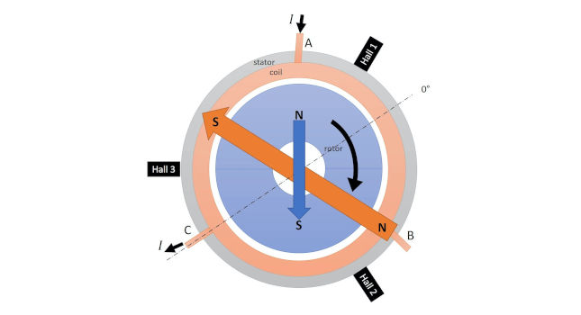
Figure 2: Schematic cross section of a slotless brushless DC motor starting Step 3. The blue area is the rotor with a two-pole permanent magnet. The magnetic field generated by the magnet is represented by the blue arrow. The orange area is the three-phase winding. When the current is flowing from phase A to phase C, it induces a magnetic field which is represented by the orange arrow for simplification. The rotor will rotate as both arrows become aligned. The drive will commute the phases (rotating the stator magnetic field, orange arrow) to maintain an angle as close as possible to 90 degrees between the stator and the rotor magnetic fields (maximum torque generated). Courtesy: Portescap
Opening and closing the transistors in a specific sequence energizes the phases of the motor to maintain the optimal orientation of the magnetic field induced by the stator versus rotor magnet (see Figure 2, Figure 3 and Figure 4).

Figure 3: Phase current and Hall sensor state with a six-step commutation. Courtesy: Portescap
The motor can be driven in a six-step trapezoidal commutation, which is broadly used (see Figure 3), or it can be operated to achieve a more advanced vector control, also called field-oriented control (FOC), depending on the sophistication of the electronics (see Figure 4).

Figure 4: Phase current using an FOC amplifier. Courtesy: Portescap
PWM regulation for brushless dc motors
In a brush (see Figure 5) or a brushless dc motor (see Figure 6), the working point (speed and torque) of an application can vary. The amplifier’s role is to vary the supply voltage or the current, or both, to achieve the desired motion output.
There are often two different ways to vary the voltage or the current:
- Linear drivers (or linear amplifiers)
- Chopper drivers (or linear amplifiers).
Linear amplifiers adapt the power delivered to the motor by changing the voltage or current. The power that is not delivered to the motor is dissipated (lost power, see Figure 6). As a result, a large heat sink is required to dissipate the power, increasing the amplifier size and making it more difficult to integrate in the application.
A chopper amplifier modulates the voltage (and current) by switching the power transistors on and off. The primary advantage is it saves power when the transistor is off. This helps conserve the battery life of the application, produces less heating from the electronics and allows for smaller electronics size. Most of the time, chopper amplifiers are using a PWM method.

Figure 5: Motion control architecture comparison between a brush DC and a brushless DC motor. Courtesy: Portescap
The PWM method consists of varying the duty cycle at a fixed frequency (see Figure 7) to adjust the voltage or current within the desired target value. Note that one advantage of the PWM technique to chop the current versus other methods is the switching frequency is a fixed parameter. This makes it easier for electronic designers to filter generated acoustic and electromagnetic noise.

Figure 6: Example of a linear amplifier energizing the motor. The power dissipated continuously by the driver for this motor coil is: P_dissipated (amplifier) = (24 – 19) * 1 = 5W Courtesy: Portescap
When the transistor of the PWM is open 100% of the time, the voltage applied to the motor is the full bus voltage. When the transistor is open 50% of the time, the average voltage applied to the motor is half the bus voltage. When the transistor is closed 100% of the time, no voltage is applied to the motor.

Figure 7: Different PWM duty cycles. Notice that frequency is the same for all cases, whereas the average voltage (dotted line) is proportional to the duty cycle. Courtesy: Portescap
Inductance effect in brushless dc motors
A dc motor is characterized by an inductance L, a resistance R, and a back electromotive force (back-EMF) E in series. The back-EMF is a voltage caused by the magnetic induction (Faraday-Lenz law of induction) that opposes the applied voltage and is proportional to the motor speed. See Figure 8, showing the motor when the PWM is ON, and when the PWM is OFF.

Figure 8: Simplified equivalent circuit diagrams representing a DC motor when the PWM is ON (left) and OFF (right). For simplicity, the right circuit corresponds to a slow decay mode (current recirculating in the motor). Courtesy: Portescap
For now, to keep things simple, let’s not consider the back EMF.
When applying voltage or switching off voltage to a RL circuit, the inductor will oppose the change of the current. Applying a voltage U to the RL circuit, the current will follow a first-order exponential rise, whose dynamic depends on the electric time constant τ equal to the ratio L / R (see Figure 9). It will asymptotically reach the steady state value, that is, 99.7% of U / R, after 5 times the time constant.

Figure 9: Exponential current rise in a RL circuit. Courtesy: Portescap
The same exponential behavior will be observed when the RL circuit will discharge. See Figure 10.
In practice, brushless dc amplifiers have a rather high PWM frequency and do not allow the current to reach steady state. This frequency is generally above 50 kHz, so the current can be modulated properly with enough cycles occurring during each commutation step. For a PWM frequency of 50 kHz, the cycle time to close and open a transistor is equal to 20 µs. Considering a six-step commutation, the time for one commutation, one-pole pair motor running at 40,000 rpm (667Hz), would take 250 µs. This would allow at least 250/20 = 12.5 cycles of the PWM during one step of the commutation.

Figure 10: Exponential current fall in an RL circuit. Courtesy: Portescap
Brushless dc motors have an electrical time constant τ of a few hundred microseconds. The current will therefore have the time to react during each PWM cycle (see Figure 11). However, the mechanical time constant is in the range of a few milliseconds, so there is a factor of 10 between the mechanical and the electrical time constant. Therefore, the rotor of the motor itself will not have enough time to react when the voltage is switched at typical PWM frequencies. Low PWM frequencies of a few thousand Hertz may generate rotor vibrations and audible noise. It is advisable to go above the audible spectrum, meaning at least above 20 kHz.
Limits of PWM for brushless dc motors
PWM will lead to current rise and fall at each cycle. The variation between the minimum and the maximum value of the current is called the current ripple ∆I (see Figure 11). High current ripple can be problematic. It is advisable to keep it as low as possible.

Figure 11: Typical current ripple generated by a 50 kHz PWM at steady state (duty cycle of 80%) The duty cycle is the same in both cases, therefore the average current is the same. The graph at left shows a low current ripple. The RMS current value is close to the average current value. The graph at right shows a high current ripple. The RMS current value is significantly higher than the average current value. Courtesy: Portescap
The torque of a dc motor is proportional to the average current, as illustrated by the formula:

Note the average current Iavg needs to be considered for the motor torque. The average current only depends on the duty cycle and is independent of the current ripple. As observed in Figure 11, the average current is the same in both cases (same duty cycle), whereas the ripple is much different (different electrical time constant).
Unlike brush dc motors, brushless dc motors do not have brushes. High current ripple is not problematic for the lifetime itself. The current ripple will have a great impact on the motor losses, causing unnecessary heat. The current ripple will generate two types of losses:
Joules losses
The current ripple will increase the RMS (root mean square) current value, which is the value considered for Joules losses calculation. The ripple will generate additional heating, without increasing the average current, hence without increasing the torque. Notice it is a square variation in function to the RMS current.

With T being the time-period of the PWM ![]() , the RMS current can be calculated with the formula:
, the RMS current can be calculated with the formula:

Iron losses
According to Faraday’s law of electromagnetic induction (Eq. 4), the variation of the magnetic field in a conducting material will induce a voltage, which will then generate circulating currents called eddy currents.

Eddy current losses are proportional to the square of the motor speed and to the square of the motor current. Based on practical measurements, when the current ripple is high, the additional iron losses generated can become significant. It is important to keep the current ripple as low as possible.
Let’s determine the formula for the current ripple, so we can define guidelines to minimize it.
From the schematic of the motor (see Figure 8), we can derive the motor equation:

Let’s assume the variation of the current is linear over the short periods of time T_ON and T_OFF. Therefore, we can rewrite the differential equation as follows:

Assuming steady state, the current ripple is constant:

Therefore, the two equations can be combined into one:

We can simplify the equation by introducing the duty cycle D and the PWM frequency fPWM:

From which we can derive the formula of the current ripple ∆I:

The variation of the current ripple in function of PWM duty cycle is a parabola, as shown in Figure 12.

Figure 12: Current ripple vs. PWM duty cycle. Courtesy: Portescap
The maximum value of the ripple is obtained when the duty cycle is 50%, meaning D=0.5:

From Eq. 15, there are several parameters influencing:
- The power supply UPWM
- The duty cycle D
- The PWM frequency fPWM
- The inductance L.
Recommendations to minimize the current ripple in brushless dc motors
We can establish some recommendations to minimize the ripple:
Reduce or adapt the power supply voltage
The current ripple is proportional to the power supply voltage. Having a high supply voltage can be useful to reach extreme working points, requiring high speed or higher power. However, if the application does not require high speed or power, a lower supply voltage will be beneficial to reduce the current ripple. Operating under the same load point with a lower power supply voltage will also increase the duty cycle, which will reduce the current ripple even more. It is important to keep the duty cycle of the PWM as far as possible from 50%, which is the worst case (Figure 12).
Increase the PWM frequency
A higher frequency will cause a shorter cycle time of the PWM; hence the current will have less time to rise. PWM frequencies not less than 50 kHz for brushless dc motors are recommended. PWM frequencies of 80 kHz or more would be even more appropriate for motors with a very small electrical time constant.
Increase the inductance
Brushless dc motors have a very small inductance value. It is a good idea to add external inductances as they will slow down the rise and fall of the current, hence reducing the current ripple. Also, the inductance value specified is given for a PWM frequency of 1 kHz. Since the motor inductance varies depending on the PWM frequency, at a typical PWM frequency of 50 kHz, the inductance may decrease to as low as 70% of the specified value. Additional inductances of several tens of µH are often added. The optimal value of the inductance is often confirmed experimentally. The additional inductances need to be added as shown in Figure 13.

Figure 13: Brushless motor with additional line inductance. Courtesy: Portescap
Though this solution would solve the current ripple concern, it might not be easy to integrate additional inductances, especially when space is limited. Therefore, it is often wise to first explore the other two options.
PWM has many advantages and is the most widely used solution for brushless dc drivers. Setting an adequate PWM voltage and using a high PWM frequency will help reduce ripple and can avoid the use of additional inductances. Today’s cost of electronic components makes it a simple solution to go with high PWM frequency. Electronic designers should consider these parameters when developing a motion system when the size and weight of electronics is a concern (such as with portable devices with embedded electronics) or when battery life is a key criterion (additional energy dissipated by Joules losses for the internal resistance of extra inductances).
Matthieu Bouat is application engineer, Portescap. Edited by Mark T. Hoske, content manager, Control Engineering, CFE Media, mhoske@cfemedia.com.
KEYWORDS: Brushless dc motors, pulse-width modulation
CONSIDER THIS
Are you resolving challenges of selecting or developing electronics using pulse-width modulation (PWM) to drive brushless dc motors?
ONLINE
www.controleng.com/discrete-manufacturing/motors-drives
Do you have experience and expertise with the topics mentioned in this content? You should consider contributing to our CFE Media editorial team and getting the recognition you and your company deserve. Click here to start this process.

